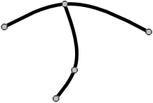
Create a design with two curves that share a knot, something like what you see on the right.
In this lesson we'll introduce the Lamp Wizard feature for designing panel lamps. We'll start, however, with some drawing commands that were not covered in earlier lessons: Yank, Group, Set Knot Location, Snap to Grid and Straighten.
If you aren't interested in the Lamp Wizard you may skip that part of this lesson, but all Glass Eye 2000 users will benefit from learning these five new commands.
Begin by starting a new, blank design. As always, be sure that Sticky is on!

Create a design with two curves that share a knot, something like what you see on the right.
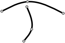
Let's say that you want to separate the lower line from the upper one by pulling it off the knot that connects the two, like what you see here.
![]() This is easy to do with the Yank command. Enter Yank mode by clicking the Yank toolbar button. If you are running in low resolution you might not see this
button on the toolbar, and you can choose "Yank" from the Edit menu instead.
This is easy to do with the Yank command. Enter Yank mode by clicking the Yank toolbar button. If you are running in low resolution you might not see this
button on the toolbar, and you can choose "Yank" from the Edit menu instead.
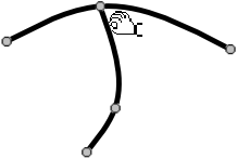
The pointer now looks like the hand on the Yank button. Position the fingertips on the line near the knot. Don't place the fingertips right
on the knot; place them on the line you want to yank, and near the knot you want to yank from, like this.
Now drag the mouse to a new location. When done, return to Pick mode.
The rule to remember about yanking is:
Collections of lines can be grouped so that they can more easily be moved in unison. Try this now by selecting both lines in your drawing (a select box is the easiest way) and then using the Group command on the shortcut menu. Notice that now when you select either line you select both. Now ungroup the lines by selecting the group and then using the Ungroup command.
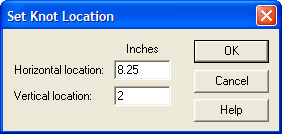
Sometimes you want to position a knot precisely by typing in its horizontal and vertical location. For example, let's set the location of the lowest knot in the design you just created. To do this, select the knot (by clicking on it) and choose "Set Knot Location" from the shortcut menu.
Whatever numbers are shown give the current location of the knot. To set a different location, type in new numbers and click OK.
In Lesson 13 you learned that when "Auto Grid Snap" is enabled, knots will snap to grid points when created or moved. Another way to use grid snapping is the "Snap to Grid" command, which causes all selected knots (or knots adjacent to selected line sections) to be moved to their nearest grid points.
![]() Try this now. First, make grid lines visible by clicking the "Show Grid" toolbar button. (The "Auto Grid Snap" feature can be on or off.) Second, select the
entire two-line design you have just created. Third, choose "Snap to Grid" from the shortcut menu. All knots will jump to their nearest grid points.
Try this now. First, make grid lines visible by clicking the "Show Grid" toolbar button. (The "Auto Grid Snap" feature can be on or off.) Second, select the
entire two-line design you have just created. Third, choose "Snap to Grid" from the shortcut menu. All knots will jump to their nearest grid points.
Close this design without saving it.
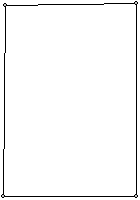 During the design process you might inadvertently cause lines that were originally straight to move out of alignment. You might also find that lines that
appeared perfectly horizontal or vertical at one zoom level are slightly out of alignment at another zoom level. In these situations, the Straighten command can help.
Let's experiment with this now. Draw a rectangle on your screen. Move the top left corner knot a very small amount so that the rectangle is out of alignment, as in the one pictured to the right. Select the entire rectangle, then choose "Straighten" from the Modify menu. The rectangle will be adjusted so that its lines are perfectly horizontal and vertical.
If the rectangle did not straighten, it could be that your lines are not close enough to being horizontal or vertical. By default, the Straighten command works on lines that are within 1° of a true horizontal or vertical line. If you'd like a different tolerance, choose "Units and Precision" from the View menu and change the value called "Straighten precision." Alternatively, you could move the top-left corner knot to make the lines closer to horizontal and vertical, and then Straighten again.
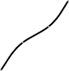 There's another way to use the Straighten command that applies to a single line only. Try it by drawing a slightly curving line like the one pictured here.
Select the entire line by double-clicking on it and then choose the Straighten command. The knots along the line will be moved so that the entire line is now straight.
Close this design without saving it.
If you've ever attempted to design your own panel lamp, you soon discovered that the mathematical calculations required to determine the size of each individual panel can be daunting. Rather than dusting off your high school trigonometry, let Lamp Wizard do those calculations for you!
Start a new design, then use the "Lamp Wizard" command on the Draw menu. (If you aren't yet licensed to use the Lamp Wizard then you'll see a message informing you of your upgrade options and letting you know the limits of this feature; click "Proceed" to continue.) You'll see this dialog box:
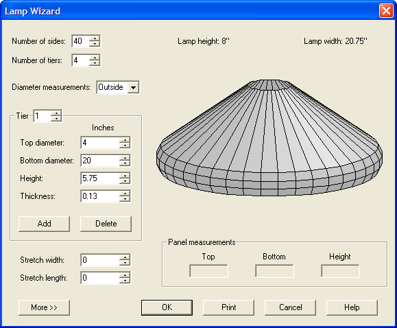
Most of the controls are self-explanatory. Have some fun changing the values and watching the effect on the lamp image. Use your mouse to turn the image and see it from all sides: just position the mouse over the image, hold down the left mouse button, and move the mouse.
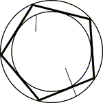
Instead of entering diameters as numeric values, you might instead prefer to specify the shape of your lamp by drawing a profile. Let's try this now. Click the "Cancel" button on the Lamp Wizard to return to a blank design. Use the Curve tool to draw a figure something like the black curve that appears in the box below, and then turn on the crosshairs and position a vertical crosshair to the right of it to specify the position of the central axis. Now select the entire line using "Select All" on the Edit menu and start the Lamp Wizard again. This time the shape of the lamp is based on your profile. You may now choose the number of sides for the lamp or make other adjustments.
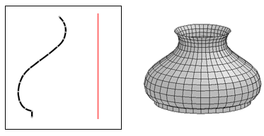
If you're licensed to use the Lamp Wizard, you can position your mouse over a panel to see its dimensions in the "Panel measurements" area. You can also click the OK button to generate a Glass Eye 2000 drawing of the panels.
Click the "Cancel" button on the Lamp Wizard to conclude this lesson.
Next Lesson: Multiple Designs and Views